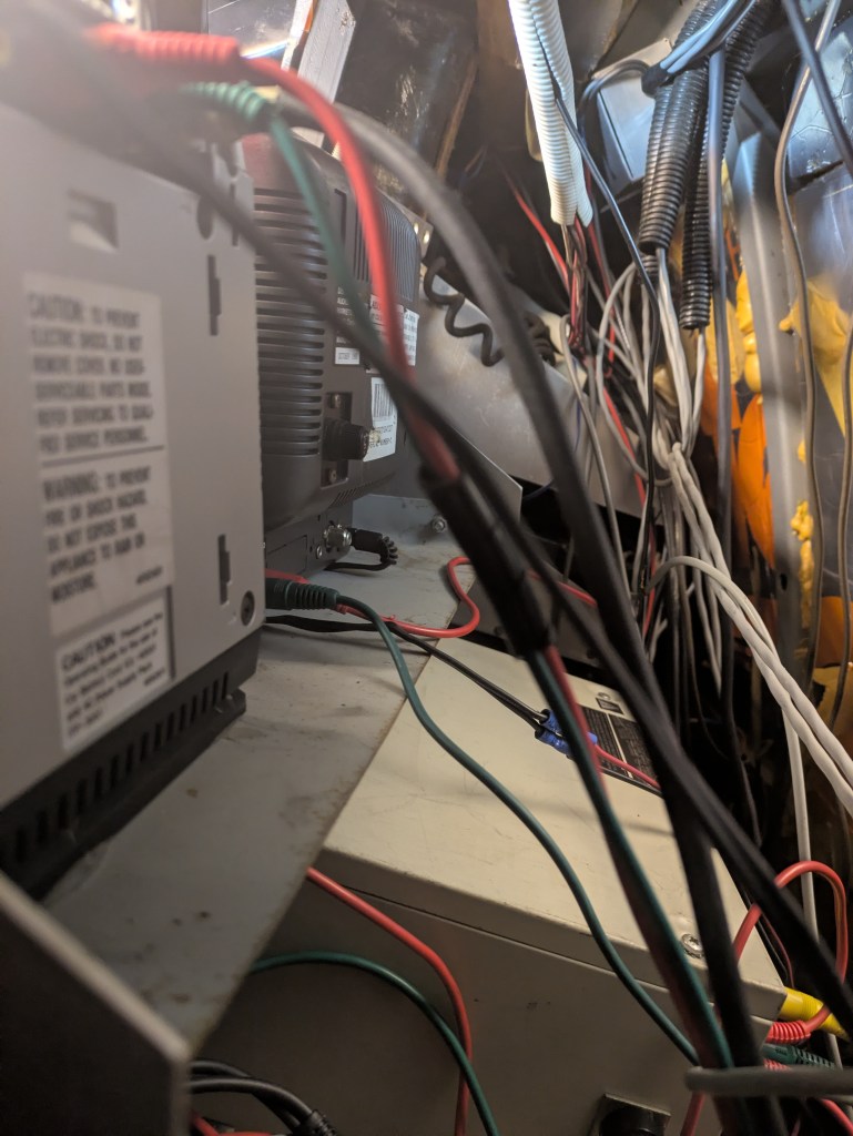
If Case File 010 was about the “Why” (FBI standards and stress), Case File 011 is about the “How.” After hours of tracing dusty cables and following wires through the dark corners of the rack, the nervous system of this van has finally been (partially) mapped.
The “Dual-Stream” Logic
The most striking discovery in the wiring is that this van was designed to record two different “truths” at the same time. It wasn’t just recording a video; it was creating a redundant, multi-perspective evidence chain.
1. The Master Feed (VCR 1 & The Large CRT)
This was the “money shot.”
- The Visual: The video signal flows from the periscope, through a RadioShack Switcher, into the Burle PTZ Controller, and finally into VCR 1. This means the master tape recorded every move the detective made with the joystick.
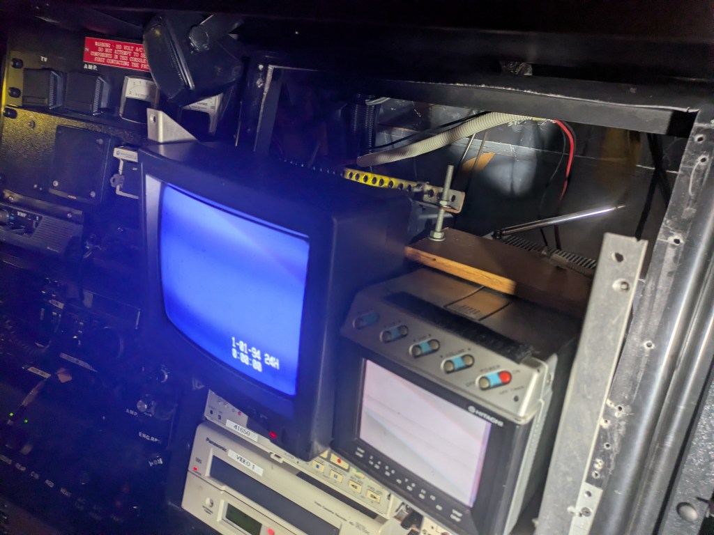
- The Goal: This tape captured the “Target.” It recorded what the target was doing. It was monitored on the Large CRT—the primary focus of the lead investigator. It is not yet clear what the audio source for VCR 1 would have been.
2. The Ambient Feed (VCR 2 & The Hitachi Stack)
This was the “Context.”
- The Visual: Video flows directly from the switcher to VCR 2.
- The Audio: Controlled by an Archer Selector, this deck primarily recorded the Shure Mixer (outside ambient mics).
- The Goal: While VCR 1 focused on the target, VCR 2 recorded the environment. If a car honked, a door slammed, or a backup team arrived, this deck caught the “big picture.” It was monitored on the smaller Hitachi CRT.
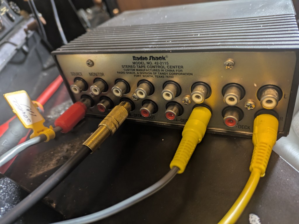
The “RadioShack Hack”
Another interesting forensic detail is the use of consumer-grade RadioShack and Archer selectors.
- Input 4 (Archer): This is wired as a “feedback loop” from VCR 1. It may have allowed the operator to take audio already recorded on the Master tape and “dub” it onto Marantz Tape Deck 2 for a detective to take back to the station in a cassette format immediately.
- Deck 3 (RadioShack): A lone video cable pokes out the front of the stack. This was the “Aux” port—likely for a “Bumper Cam” or a handheld unit used when a target moved out of the periscope’s line of sight.
The Green Wire
Amongst the meticulously labeled system, Tape Deck 1 sits with a lone Green Wire unplugged and silent. In a world where every cable has a purpose, this “Empty Channel” is a reminder that surveillance is unpredictable. Was it for a specialized piece of gear? A long-range parabolic mic? Or simply a spare for when the primary system failed?
The following is the beginning of a map of where the various audio and video inputs/outputs go.
I. Video Routing Matrix
Controlled by the RadioShack 42-2115 Switcher
| Switcher Port | Direction | Connected To |
| Source Input | IN | Periscope Camera |
| Deck 3 Input | IN | Auxiliary Wire (poked out front of stack) |
| Deck 1 Output | OUT | Burle PTZ Controller (Video In) |
| Deck 2 Output | OUT | VCR 2 (Video In) |
II. Audio Routing Matrix
Controlled by the Archer Switcher
| Switcher Port | Direction | Connected To |
| Input 2 | IN | VHF Radio 2 (“Audio from VHF 2” wire) |
| Input 3 | IN | Shure Mixer (Outside Ambient Mics) |
| Input 4 | IN | VCR 1 (Audio Out Feed) |
| Output Channel A | OUT | Marantz Tape Deck 2 (Line In) |
| Output Channel B | OUT | VCR 2 (Audio In) |
III. Dedicated Monitor & Master Loops
Hardwired for direct verification (does not go through switchers)
| Source Device | Connection Type | Destination |
| VCR 1 | Audio & Video Out | Large CRT Monitor (Master View) |
| VCR 2 | Audio & Video Out | Hitachi CRT Monitor (Secondary View) |
| Burle PTZ | Video Out | VCR 1 (Video In) |
IV. Isolated/Direct Audio Wires
Manual connections found during the forensic teardown
| Device | Wire Color | Status / Connection |
| VCR 1 | Grey | Runs from VCR 1 Audio In toward the Radio Stack, unknown destination. |
| Tape Deck 1 | Green | Disconnected (Not plugged into anything) |
Since the last tech update, VCR2 seems to have stopped functioning. This isn’t unexpected, due to the sheer scope of this project we expected some setbacks.

Leave a comment